SegDSee 4
User’s Manual
Contents
Open folder to browse SEG-D,
SEG_B files
Change scale and gain by mouse wheel
Introduction
The SegDSee program displays headers
and seismic data from disk SEG-D or SEG-B file
- Single shot file and Lacey
Tape on Disk (LTOD) encapsulation is supported
- Currently supported formats: SEG-D Rev 0 - 3.1 and Standard SEG-B
Starting
the program
|
Double click program icon by mouse: Main window will be shown |
|

Using
the program
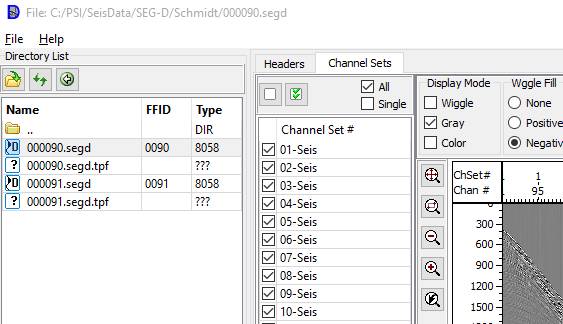
Open
folder to browse SEG-D, SEG_B files
Select “File”
→ “Open Directory”
menu item. “Open” dialog will be shown.
Use it for directory selection.
Buttons in file browser panel:
![]() - Return to the previous directory
- Return to the previous directory
![]() - Refresh directory list
- Refresh directory list
![]() - Open directory selection dialog
- Open directory selection dialog
To display needed file select it by mouse. Also it is possible to select file by ↑ and ↓ arrow keys from keyboard.
Selected valid SEG-D or SEG-B file will be displayed in Data Panel.
For going to upper directory level double click or
press Enter on ![]() item in the list.
item in the list.
LTOD file content is opening by double clicking or
pressing Enter on corresponding item.
To exit from LTOD content list double click or press Enter on ![]() item.
item.
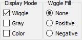
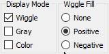
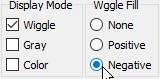
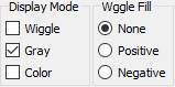
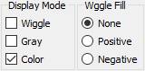
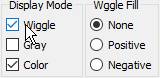
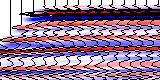
Display mode selection.
“Display mode” and “Wiggle Fill”
panels
The modes and corresponding controls’ positions
are shown in the following table
|
|
Mode |
Controls position |
Seismic sample |
|
1 |
Wiggle |
|
|
|
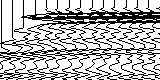
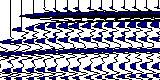
2 |
Wiggle + Positive Fill (Variable area) |
|
|
|
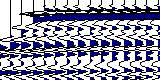
3 |
Wiggle + Negative Fill |
|
|
|
4 |
Variable density (Gray levels) |
|
|
|
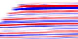
5 |
Color |
|
|
|
6 |
Color + Wiggle |
|
|

|
Display
Mode panel controls |
Description |
|
Wiggle |
Wiggle mode |
|
Gray |
Variable density mode |
|
Color |
Color mode |
|
Wiggle
Fill panel controls |
Description |
|
None |
No wiggle fill |
|
Positive |
Positive fill |
|
Negative |
Negative fill |
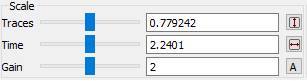
Scaling
and Gain Setup
Scale
Panel
|
Scale
panel controls |
Description |
|
Traces |
Set trace number per centimeter |
|
|
Fit seismic section to window horizontally |
|
Time |
Set time scale (cm/sec) |
|
|
Fit seismic section to window vertically |
|
Gain |
Wiggle Gain control |
|
|
Automatically adjust current wiggle gain,
using maximal amplitude values of selected trace |
|
Gain |
Gain control |
To adjust a value by mouse, move mouse cursor
to the corresponding slider (![]() ),
then press left mouse button, and (keeping it pressed) move the slider. Current
value of the parameter will be shown in edit control that is on the right of
the slider, and seismic image will be repainted to reflect the changes.
),
then press left mouse button, and (keeping it pressed) move the slider. Current
value of the parameter will be shown in edit control that is on the right of
the slider, and seismic image will be repainted to reflect the changes.
Change scale
and gain by mouse wheel
|
Mouse
Position during Wheel rotating |
Action |
|
In the Traces input filed, In the Time Axis |
Change horizontal
scale |
|
In the Time input field, In the Headers Axis |
Change vertical
scale |
|
In the Seismic Section window |
Zoom-In/Zoom-out in
both directions |
|
It the Gain-w input field |
Change Wiggle mode
gain |
|
In the Gain-с input field |
Change Color mode
gain |
Zoom buttons.
Button
|
Description |
|
|
Fit all
the image to seismic window size |
|
|
Zoom by
window. Press this button then draw a rectangle on the seismic window (move
mouse cursor to first corner of the rectangle, press left mouse button, and
keeping it pressed, move mouse to set desired size). Selected region will be
zoomed to size of the seismic window. |
|
|
Return to
previous zoom |
|
|
Zoom in
(1.5 times) |
|
|
Zoom out
(1.5 times) |
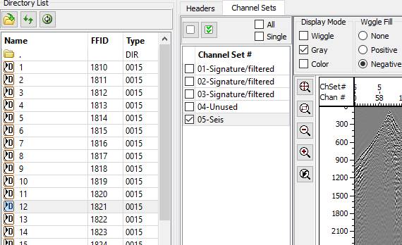
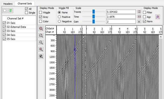
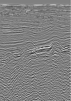
Seismic
Channel Sets Display
To display
seismic view panel select “Channel Sets” tab.
![]()
When you move mouse pointer in the seismic
window, values corresponding current position will be shown in status bar at
the bottom of the main window
|
T |
Time (ms) |
on mouse
moving |
|
Ch.Set |
Channel set # |
on trace selecting |
|
Chan |
Cannel # |
on trace selecting |
|
FFID |
FFID # |
on trace selecting |
|
SP |
Shot Point # (if exists) |
on trace selecting |
Left panel contains channel set list:
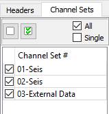
The panel
has the following controls:
|
Control |
Name |
Description |
|
|
Selection
mode |
All – all channel sets are always selected ,
Single – only marked |
|
|
unmark
all sets |
in Single
mode |
|
|
mark all
sets |
in Single mode |
In “All” selection mode all channel sets always will shown
In “Single” mode you should
check ![]() channel sets, which
need to be shown and uncheck others.
channel sets, which
need to be shown and uncheck others.
Display
seismic file headers
To activate
headers panel select “Headers” tab.
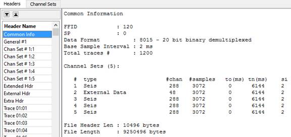
In the left panel, headers list is shown, at the right – content of the selected header.
“Common info” item is not a header, it holds
common description of current SEG-D or SEG-B file.
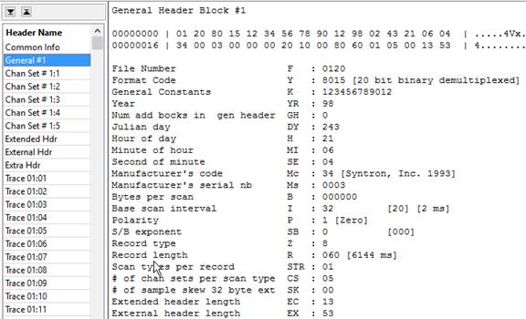
At the top of content window selected header
bytes are displayed (in hexadecimal and ASCII formats), and after that these
data are shown in parsed form.
Header name
General
Header Block #1
Data Dump
00000000
| 01 20 80 15 12 34 56 78 90 12 98 02 43 21 06 04 | .....4Vx....C!..
00000016
| 34 00 03 00 00 00 20 10 00 80 60 01 05 00 13 53 | 4.........`....S
Parsing
File
Number F : 0120
Format
Code Y : 8015 [20 bit binary demultiplexed]
General
Constants K : 123456789012
Year
YR : 98
Num
add bocks in gen header GH : 0
Julian
day DY : 243
Hour
of day H : 21
Minute
of hour MI : 06
Second
of minute SE : 04
Manufacturer's
code Mc : 34 [Syntron, Inc. 1993]
Manufacturer's
serial nb Ms : 0003
Bytes
per scan B : 000000
Base
scan interval I : 32 [20] [2 ms]
Polarity
P : 1 [Zero]
S/B
exponent SB : 0 [000]
Record
type Z : 8
Record
length R : 060 [6144 ms]
Scan
types per record STR : 01
# of
chan sets per scan type CS : 05
# of
sample skew 32 byte ext SK : 00
Extended
header length EC : 13
External
header length EX : 53
Seismic Data
Processing
Processing
is applied to trace before it will be shown on screen. Here is the processing
modules list:
-
band
pass filter
-
automatic
gain control (AGC)
Processing
parameters setup
To set the processing parameters press ![]() button or select “Processing” ® “Parameters” menu item, after that
“Processing” dialog appears. Enter parameters needed. To accept the parameters
press “Apply” or “OK” button. “OK” also closes the dialog. “Close” button discards
any changes and closes the dialog.
button or select “Processing” ® “Parameters” menu item, after that
“Processing” dialog appears. Enter parameters needed. To accept the parameters
press “Apply” or “OK” button. “OK” also closes the dialog. “Close” button discards
any changes and closes the dialog.
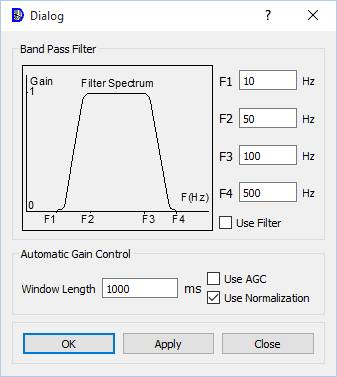
Band pass
filter
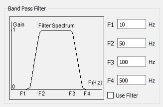
Enter filter cut frequencies as it is shown in
the picture and check “Use filter”, if you want to use the filter.
|
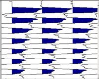
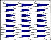
Original data |
Filtered data |
|
|
|
Automatic gain control (AGC)
In “Use Normalization” mode maximum amplitude
value is calculated for trace and each sample is divided to its value.
In “Use AGC” mode “Window length” parameter
sets AGC window length. AGC module moves the window down the trace sample-by-sample
and calculates a scale factor at each location. The scale factor is equal to
the RMS amplitude in the window.

Enter “Window length” and check “Use AGC”, if
you want to use the AGC.
|
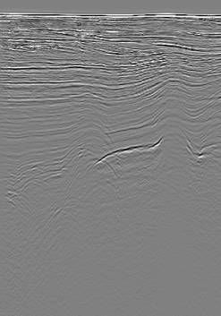
Original data |
AGC applied |
|
|
|
© Sergey Pavlukhin
Yuzhno-Sakhalinsk, Russia
2019